Our sales team will be happy to assist you with any technical questions you may encounter. Feel free to call our toll free number 800-642-1357 or email to sales@nationalbasicsensor.com. A PDF of the technical reference portion of our catalog shown below is available for download here. Individual sections of the technical reference pages can be downloaded below.
When there is a temperature difference between these two junctions, a small electromotive force (emf) is developed. An emf will originate not only at the hot junction but there is also the potential of the same wherever there is a temperature gradient between parts of the same wire.
1800 - Alessandro Volta concluded that Galvani’s frog twitched when contacted by two dissimilar metals.
1821 - Thomas I. Seebeck discovered the existence of thermoelectric currents.
1821 - Jean Baptiste Joseph Fourier published his basic heat conduction formula.
1826 - George S. Ohm discovered his equation for electrical conduction.
1834 - Jean Charles A. Peltier found out that when a current flows across the junction of two metals, it absorbs or releases heat.
1840 - James Prescott Joule found the important I2R heating effect.
1850 - Rudolf Julius Emanuel Clausius introduced the concept of entropy.
1851 - William Thomson (Lord Kelvin) discovered that an electric current produces different thermal effects.
states that a circuit of a single homogeneous wire cannot maintain a current by means of heat application alone.
B. The Law of Intermediate Metals
states that the algebraic sum of the thermo-electromotive forces in a circuit composed of any number of dissimilar materials is zero if all of the circuit is maintained at a uniform temperature.
C. The Law of Intermediate Temperatures
states if one junction of a circuit of two dissimilar homogeneous wires is maintained at one temperature and the other junction is at another temperature, the thermal emf developed is independent of the temperature gradient along the wires.
D. The Fundamental Law
of the above three may be stated as the algebraic sum of the thermo-electromotive forces generated in any given circuit containing any number of dissimilar homogeneous metals, is a function only of the temperatures of the junctions.
Thermoelectric relationships of the various thermo-elements are charted against platinum 67 as a standard. Each alloy on the chart is thermoelectrically negative in respect to all those above it and positive with respect to all those below it.

(2) An averaging thermocouple consisting of two or more thermocouples connected in parallel to a common cold junction. The emf generated will correspond to the mean of the temperatures of the individual junctions.

(3) A thermopile consists of two or more thermocouples connected in series. The resultant emf generated will be the aggregate of all individual junctions.

(4) A Delta thermocouple, sometimes known as a differential thermocouple, may consist of two similar wires. “A” joined to a single dissimilar wire “B” with the two measuring junctions normally at different temperatures. The resultant emf will be the difference between the two junctions, usually referred to as the differential temperature.

Care should be taken that there are no grounds in the circuit they will develop thermal emf’s.
Thermocouple Theory and Development
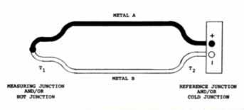
I - The Thermocouple
A thermocouple is composed of two dissimilar metals, usually in wire form, joined together at one end to form the measuring or “hot” junction, while the other end is known as the reference or “cold” junction.When there is a temperature difference between these two junctions, a small electromotive force (emf) is developed. An emf will originate not only at the hot junction but there is also the potential of the same wherever there is a temperature gradient between parts of the same wire.
II - Historical Development of the Thermocouple
The theory of thermoelectric effects was not established by one man at one time but is the culmination of various scientists over a span of many years. Here in chronological order are some of the people who developed the elementary principles of thermoelectric thermometry.1800 - Alessandro Volta concluded that Galvani’s frog twitched when contacted by two dissimilar metals.
1821 - Thomas I. Seebeck discovered the existence of thermoelectric currents.
1821 - Jean Baptiste Joseph Fourier published his basic heat conduction formula.
1826 - George S. Ohm discovered his equation for electrical conduction.
1834 - Jean Charles A. Peltier found out that when a current flows across the junction of two metals, it absorbs or releases heat.
1840 - James Prescott Joule found the important I2R heating effect.
1850 - Rudolf Julius Emanuel Clausius introduced the concept of entropy.
1851 - William Thomson (Lord Kelvin) discovered that an electric current produces different thermal effects.
II - Laws of Thermoelectricity
A. The Law of the Homogeneous Circuitstates that a circuit of a single homogeneous wire cannot maintain a current by means of heat application alone.
B. The Law of Intermediate Metals
states that the algebraic sum of the thermo-electromotive forces in a circuit composed of any number of dissimilar materials is zero if all of the circuit is maintained at a uniform temperature.
C. The Law of Intermediate Temperatures
states if one junction of a circuit of two dissimilar homogeneous wires is maintained at one temperature and the other junction is at another temperature, the thermal emf developed is independent of the temperature gradient along the wires.
D. The Fundamental Law
of the above three may be stated as the algebraic sum of the thermo-electromotive forces generated in any given circuit containing any number of dissimilar homogeneous metals, is a function only of the temperatures of the junctions.
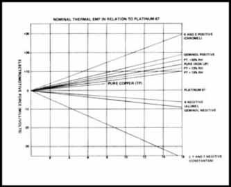
IV - Polarity of Some Thermocouple Materials
Thermoelectric relationships of the various thermo-elements are charted against platinum 67 as a standard. Each alloy on the chart is thermoelectrically negative in respect to all those above it and positive with respect to all those below it.
V - Thermocouple Materials
Composition of and practical use are explained in detail on page 150.VI - Thermocouple Wiring Arrangments
(1) Standard single thermocouple consisting of two dissimilar wires and a single measuring junction.(2) An averaging thermocouple consisting of two or more thermocouples connected in parallel to a common cold junction. The emf generated will correspond to the mean of the temperatures of the individual junctions.
(3) A thermopile consists of two or more thermocouples connected in series. The resultant emf generated will be the aggregate of all individual junctions.
(4) A Delta thermocouple, sometimes known as a differential thermocouple, may consist of two similar wires. “A” joined to a single dissimilar wire “B” with the two measuring junctions normally at different temperatures. The resultant emf will be the difference between the two junctions, usually referred to as the differential temperature.
Care should be taken that there are no grounds in the circuit they will develop thermal emf’s.
VII - Thermocouple Protective Materials
Composition of and practical use explained in detail on pages 152-153.VIII - Installation Principles
A. Thermocouples- A sufficient depth of immersion should be provided for so that the measuring junction is entirely into the medium to be measured. This is to prevent heat being conducted away from the measuring junction. Basic rule of thumb for minimum immersion depth is 10 times the sheath diameter.
- Avoid direct flame impingement.
- A thermocouple reports only what it “feels.”
- In a high temperature environment, install the thermocouple in a vertical position. Otherwise, a support should be provided to prevent sagging of the protection tube.
- The connecting head and reference junction must be at ambient temperature. Serious errors can occur if this point is overlooked.
- Preheat refractory protection tubes before installation.
- Check thermocouples in place - on a regular basis.
- Replace burned out protection tubes at once.
- Do not use a type K thermocouple below 1000°F if prior usage was above 1000°F.
- Do not change the immersion depth of a thermocouple after it has been in service.
- Select largest wire gauge or sheath diameter possible for longest life, or as small as possible for fastest response.
- Be sure the extension wire is the same calibration as the thermocouple.
- Select the proper insulation.
- Observe the color coding - Red is negative.
- Where possible, install wire in a conduit.
- Never run electrical wire in the same conduit as thermocouple extension wires.
- Never run thermocouple wires parallel or across any AC electric line.
- Do not use extension wire in place of insulated thermocouple wire.
- If you must splice, solder and tape to avoid grounding or shorting of the splice.
- Do not contaminate the wires with solvents or oil.
- If thermocouples are in a series or parallel circuit, check for grounds to avoid stray emf’s.
- Select wire gauge to be compatible with terminal screws yet sufficient size to meet loop resistance requirement.
